As processors, power electronics, batteries and industrial systems continue to increase in power density, removing heat efficiently has become one of the most important challenges in modern equipment design.
Traditional air cooling works well for many applications, but increasing heat flux, limited installation space and stricter temperature requirements are driving engineers toward liquid cooling.
At the center of many liquid cooling systems are Liquid Cold Plates.
Liquid cold plates transfer heat directly from CPUs, GPUs, IGBT modules, batteries, inverters, lasers and other high-power components into a circulating coolant. By positioning the coolant close to the heat source, a properly designed cold plate can provide high cooling capacity, controlled component temperatures and a compact thermal solution.
But liquid cold plates are not all the same.
Their performance depends on the material, coolant channel geometry, flow rate, pressure drop, heat-source distribution, joining process and overall cooling-system design.
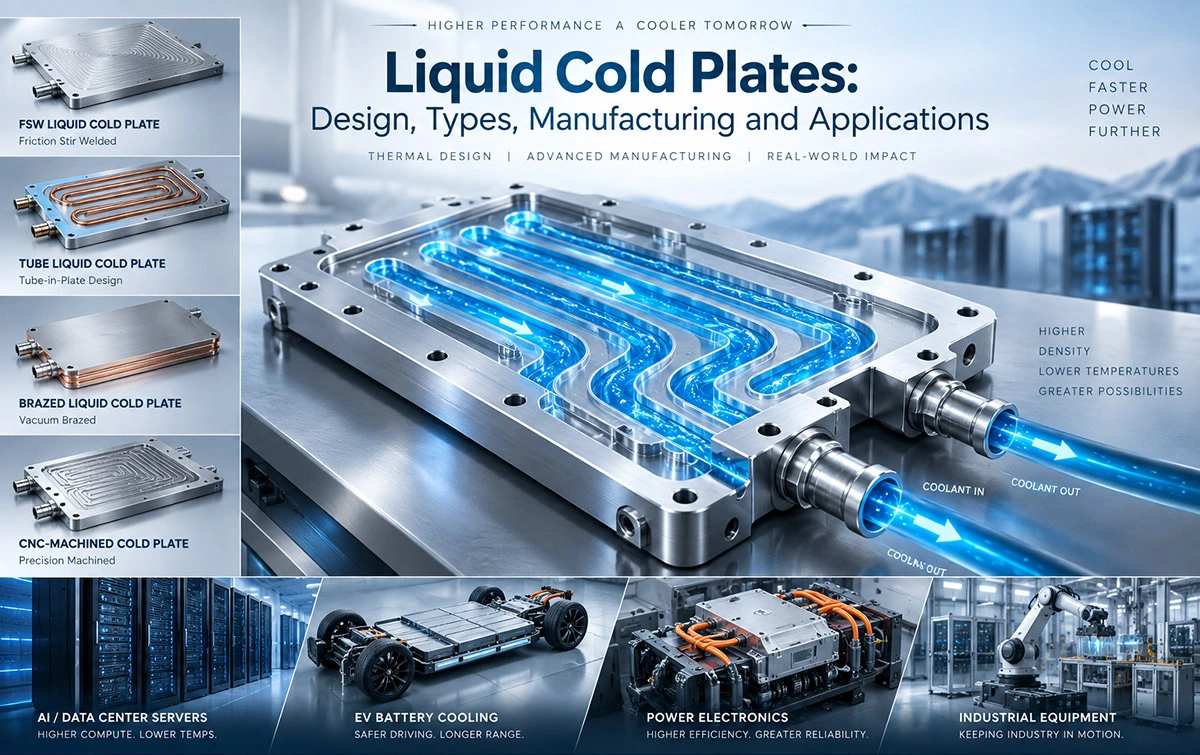
This guide explains how liquid cold plates work, the main types available, manufacturing technologies, materials, design considerations and applications.
What Are Liquid Cold Plates?
A liquid cold plate is a heat exchanger designed to remove heat from a component or assembly through circulating liquid.
The cold plate normally consists of a thermally conductive metal body containing internal coolant channels.
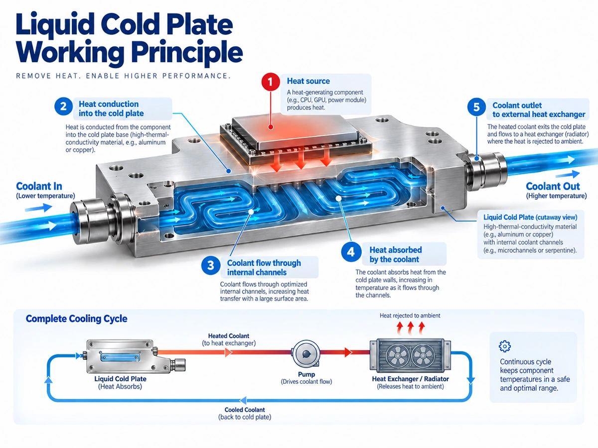
A heat-generating device is attached to the cold plate surface. Heat travels from the component through the contact interface and into the metal plate. Coolant flowing through internal channels then absorbs the heat and carries it away.
The basic thermal path can be represented as:
Heat Source → Thermal Interface → Cold Plate → Coolant → Heat Exchanger
After leaving the Liquid Cooling Plate, the heated coolant normally flows toward a radiator, chiller, coolant distribution unit or another heat exchanger before returning to the cold plate.
This makes the cold plate the thermal interface between the heat-generating component and the complete liquid cooling system.
How Do Liquid Cold Plates Work?
Liquid cold plate cooling relies primarily on two heat-transfer mechanisms: conduction and convection.
Heat Conduction
The CPU, GPU, battery cell, power module or other heat-generating component is mounted against the cold plate.
Heat conducts from the component into the metal body of the cold plate.
The contact surface is particularly important. Poor flatness, insufficient mounting pressure or excessive thermal interface material thickness can increase contact thermal resistance before heat even reaches the coolant.
Liquid Convection
Coolant enters through the cold plate inlet and flows through channels positioned close to the heat-generating area.
As the liquid moves through these channels, heat transfers from the metal walls into the coolant.
The heated coolant then exits the cold plate and transports the thermal energy away from the device.
For a simplified liquid cooling loop, the amount of heat absorbed by the coolant can be expressed as:
Q = ṁ × Cp × ΔT
Where:
Q = heat transferred
ṁ = coolant mass flow rate
Cp = specific heat capacity of the coolant
ΔT = coolant temperature increase
This relationship explains why coolant type and flow rate are important when designing a liquid cold plate system.
Why Use Liquid Cold Plates?
The main reason engineers move from air cooling to liquid cooling is increasing heat density.
A large air-cooled heat sink requires enough fin area and airflow to dissipate heat into the surrounding environment. As power increases, the required heat sink and fan system can become increasingly large.
Liquid cold plates allow heat to be collected at the component and transported to another location for heat rejection.
This provides several advantages.
| Consideration | Liquid Cold Plate | Air-Cooled Heat Sink |
|---|
| Heat-transfer medium | Liquid | Air |
| High-power density | Excellent suitability | Increasingly difficult |
| Heat rejection location | Can be remote | Usually close to device |
| Space around heat source | Compact | Requires fins and airflow |
| Pump | Required | Not required |
| Fan | Not required at cold plate | Usually required for high power |
| System complexity | Higher | Lower |
| Leakage management | Required | Not applicable |
Liquid cooling should therefore not automatically be considered better for every application.
For lower heat loads, an extruded or skived heat sink may provide a simpler and more economical solution.
Liquid cold plates become particularly attractive when power density, temperature requirements or installation constraints make conventional air cooling impractical.
Main Types of Liquid Cold Plates
The term liquid cold plate describes the thermal function rather than one specific manufacturing technology.
Different manufacturing processes can be selected according to heat load, flow-channel complexity, operating pressure, cost, production quantity and reliability requirements.
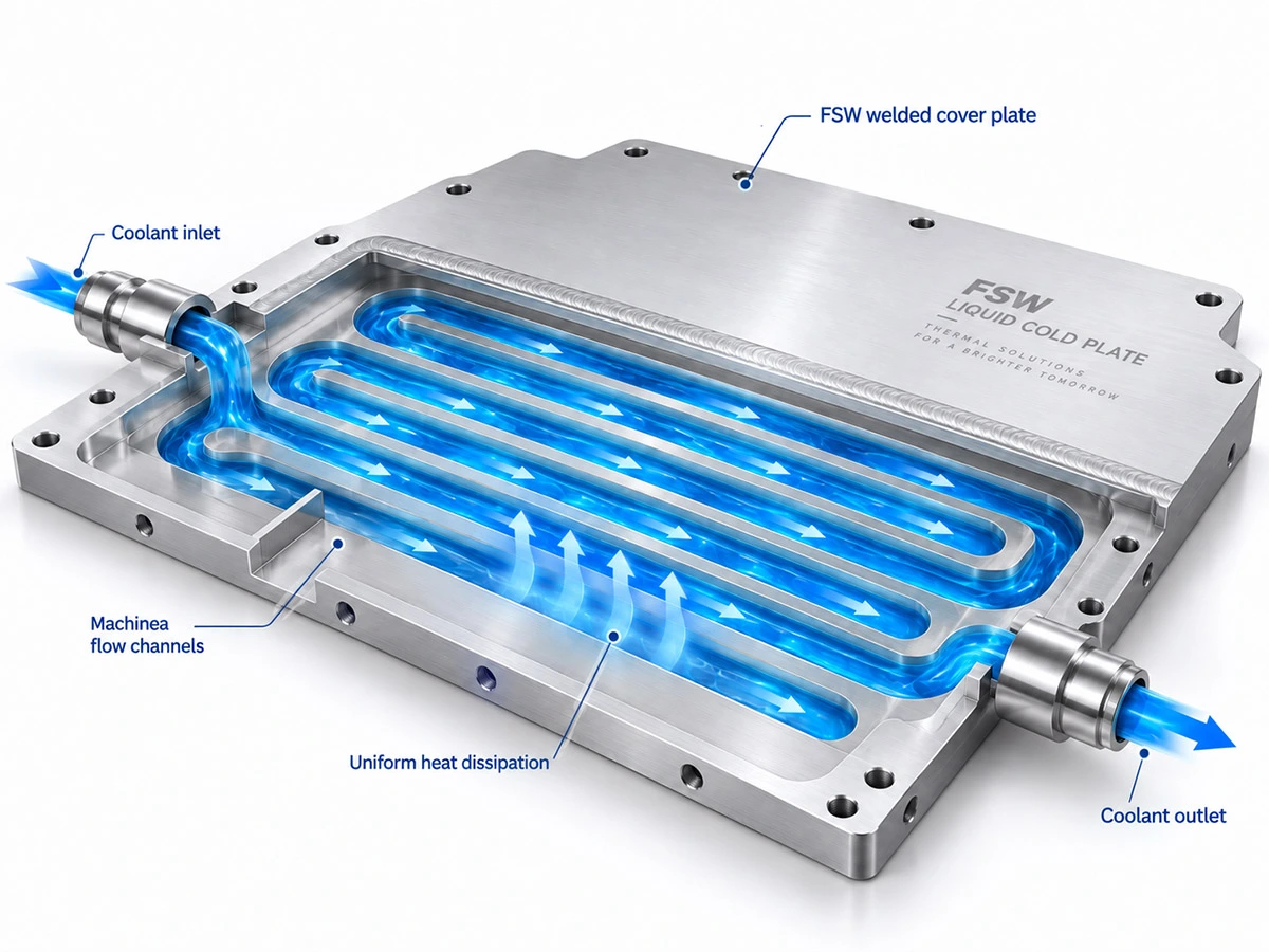
An FSW Liquid Cold Plate uses Friction Stir Welding to seal CNC-machined cooling channels.
The typical process begins with an aluminum base plate. CNC machining creates the required internal channel geometry. A cover plate is then positioned above the channels and joined using Friction Stir Welding.
FSW is a solid-state joining process. Instead of completely melting the material, a rotating tool generates frictional heat and mechanically joins the softened materials.
This manufacturing method provides substantial freedom for internal channel design.
Channels can be positioned close to concentrated heat sources, allowing engineers to optimize coolant distribution around CPUs, GPUs, IGBTs and other high-power devices.
FSW cold plates are commonly considered for:
Data center and AI computing equipment, EV power electronics, battery systems, energy storage equipment, inverters, industrial electronics and other high-power thermal applications.
2. Tube Liquid Cold Plate
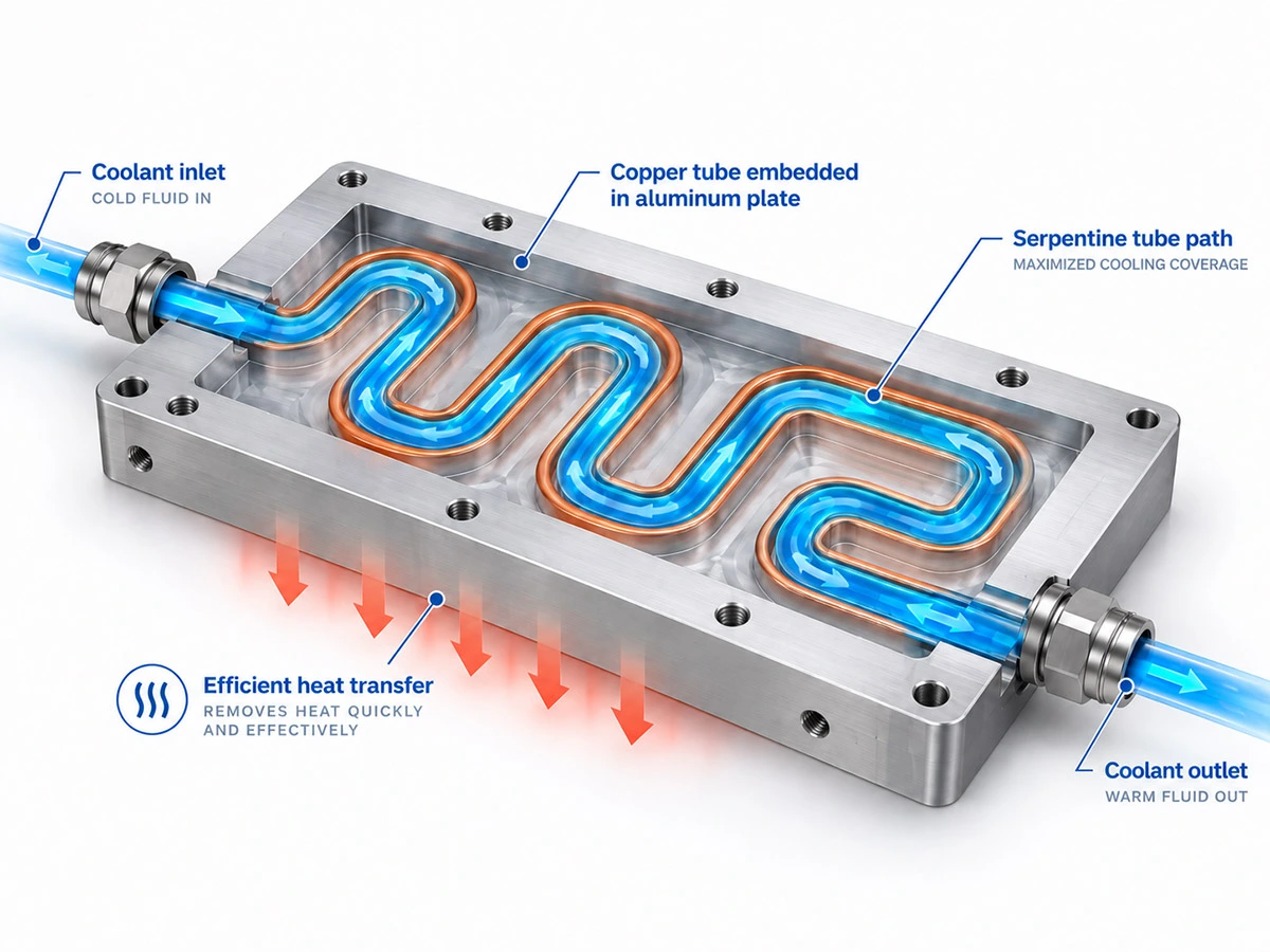
A tube liquid cold plate uses a formed tube embedded into a metal plate.
Copper tubing is commonly combined with an aluminum base because copper provides excellent thermal conductivity and corrosion resistance within the coolant path while aluminum reduces weight and cost.
The tube can be formed into a serpentine cooling path underneath the heat-generating areas.
Compared with complex machined channel structures, an embedded tube cold plate can provide a relatively simple and economical solution.
Tube cold plates are frequently used in battery systems, converters, power supplies, motor drives, industrial electronics and renewable-energy equipment.
The key design consideration is tube routing.
The tube needs to pass sufficiently close to the primary heat sources while avoiding excessive length and hydraulic resistance.
3. Brazed Liquid Cold Plate
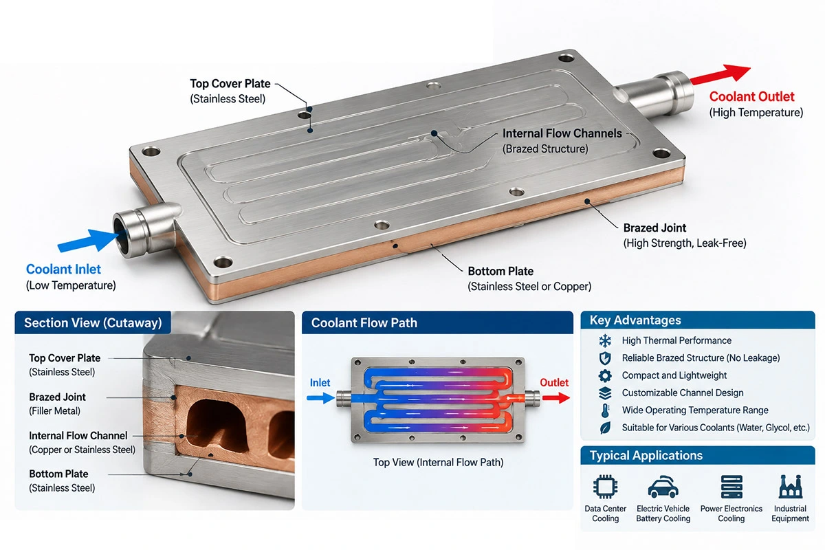
A brazed liquid cold plate is manufactured by joining multiple metal components through a brazing process.
The base, cover and internal cooling structures can be manufactured separately before being joined.
This gives engineers significant freedom when designing internal flow structures.
Internal fins, pin structures, channels or other heat-transfer features can be incorporated to increase surface area between the coolant and cold plate.
Vacuum brazing is frequently used for aluminum liquid cold plates because it can produce a compact structure with complex internal geometries.
Brazed cold plates are widely used for power electronics, semiconductor equipment, medical systems, lasers and other high-performance thermal management applications.
4. CNC Machined Liquid Cold Plate
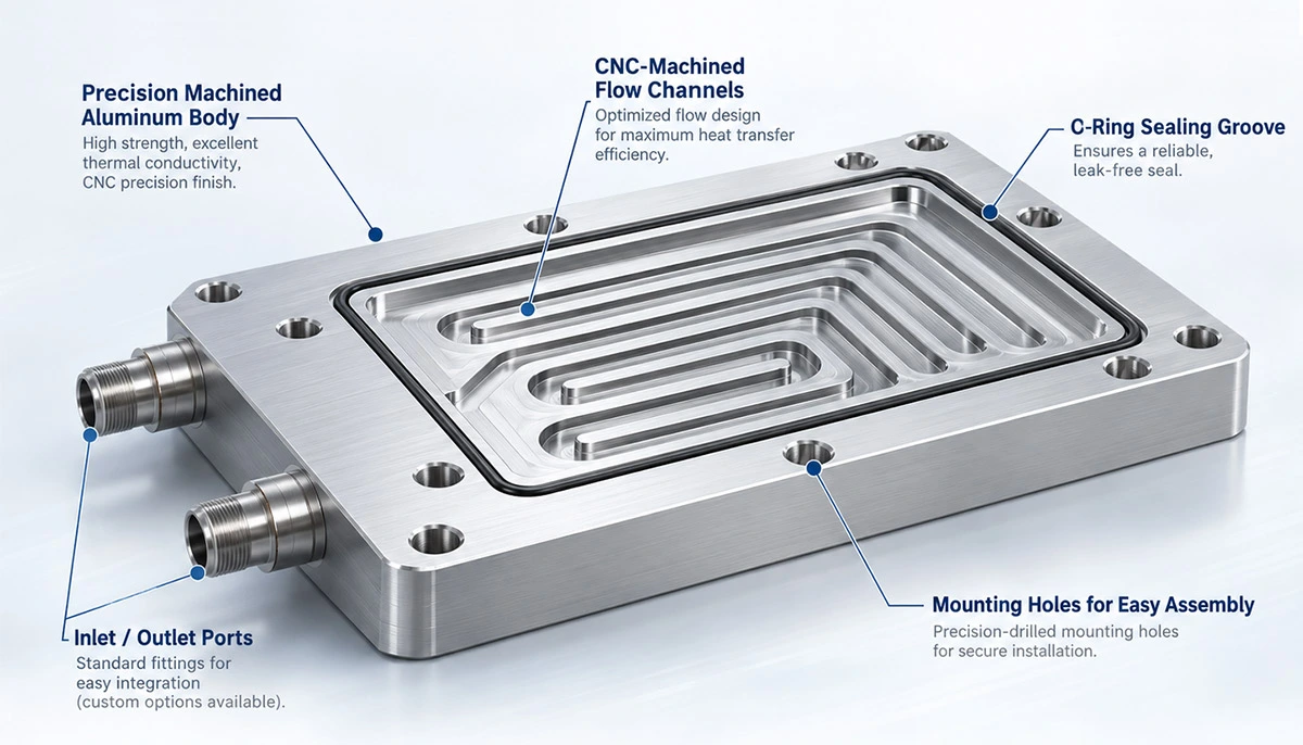
CNC machining can be used to produce precision coolant passages directly inside aluminum or copper components.
Depending on the design, the plate may use machined channels combined with a cover or intersecting drilled passages.
CNC machining is particularly useful for prototypes and highly customized cold plates because channel locations, mounting features and external dimensions can be adapted to a specific project.
5. Extruded Liquid Cooling Plate
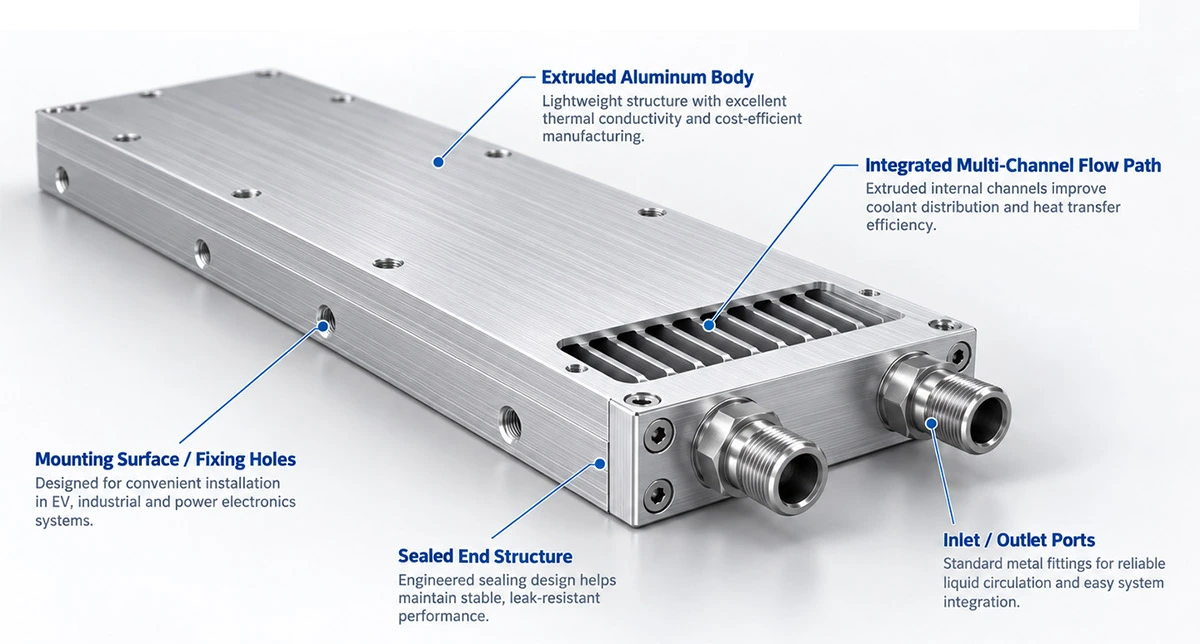
Extrusion can produce aluminum profiles containing integrated longitudinal cooling channels.
The profile is subsequently cut and machined to the final dimensions before the ends and coolant connections are completed.
Extrusion is well suited to designs requiring a consistent channel cross section and relatively high production quantities.
However, internal channel geometry is more restricted than with fully CNC-machined cold plates.
FSW vs Tube vs Brazed Liquid Cold Plates
There is no manufacturing technology that is ideal for every cold plate.
The correct process depends on the application.
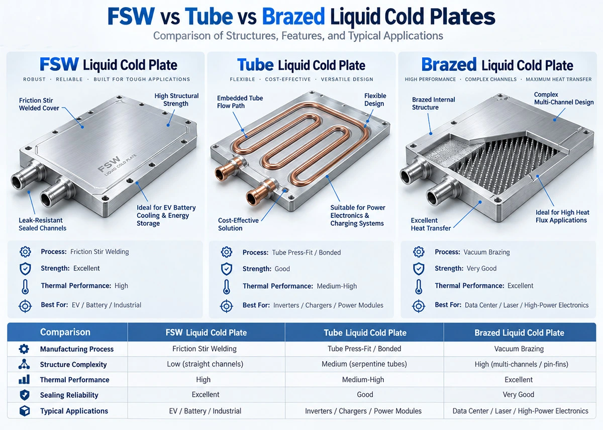
| Cold Plate Type | Channel Flexibility | Manufacturing Complexity | Typical Use |
|---|
| FSW | High | Medium–High | AI, power electronics, EV, industrial |
| Tube | Medium | Medium | Battery, inverter, power supply |
| Brazed | Very High | High | Semiconductor, laser, medical, power electronics |
| CNC Machined | High | Medium–High | Prototype and customized systems |
| Extruded | Lower | Low–Medium | Repeatable higher-volume designs |
Rather than selecting a manufacturing process first, engineers should start with the thermal and hydraulic requirements.
The manufacturing method can then be selected according to the channel structure required to achieve those targets.
Aluminum vs Copper Liquid Cold Plates
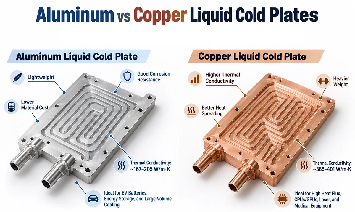
Aluminum and copper are the two most common materials used in liquid cold plate manufacturing.
Aluminum Liquid Cold Plates
Aluminum combines relatively high thermal conductivity with low density, good machinability and competitive cost.
6061 and 6063 aluminum alloys are widely used for thermal management components.
Aluminum cold plates are particularly attractive for automotive, battery and industrial systems where reducing total equipment weight is important.
Aluminum also works well with manufacturing processes such as CNC machining, extrusion, Friction Stir Welding and vacuum brazing.
Copper Liquid Cold Plates
Copper provides substantially higher thermal conductivity than aluminum.
This makes copper attractive when heat is concentrated into a small area and rapid heat spreading is required.
Typical applications include CPU and GPU cooling, semiconductor equipment, laser systems and other high-heat-flux devices.
The trade-offs are higher density, material cost and machining cost.
Material selection should therefore consider more than thermal conductivity.
Weight, corrosion, coolant compatibility, manufacturing process and total system cost must also be evaluated.
Liquid Cold Plate Channel Design
The internal flow channel is one of the most important elements in liquid cold plate design.
Common configurations include:
Serpentine channels, parallel channels, multi-pass channels, microchannels, pin-fin structures and manifold-distributed channels.
The objective is not simply to create the largest possible number of channels.
The real design challenge is balancing heat transfer, flow uniformity and pressure drop.
Serpentine Channels
A serpentine channel forces the coolant through a defined path.
The design is simple and makes coolant distribution easy to control.
However, a long narrow channel can produce relatively high pressure drop.
Parallel Channels
Parallel channels can significantly reduce overall flow resistance.
They are useful for larger cooling areas, but inlet and outlet manifolds must distribute coolant evenly across all channels.
Poor distribution can cause some channels to receive too much flow while others receive insufficient coolant.
Microchannels
Microchannels increase the surface area between the cold plate and coolant.
They can be effective for concentrated heat loads such as processors and semiconductor devices.
The disadvantage is increased hydraulic resistance and greater sensitivity to contamination or blockage.
Pin-Fin Structures
Pin-fin cold plates use internal pins to increase surface area and disrupt coolant flow.
They can provide strong heat transfer in areas with high heat flux, although pressure-drop requirements must again be considered.
Pressure Drop: A Critical Cold Plate Parameter
A common liquid cooling design mistake is optimizing only for temperature.
Increasing coolant velocity or reducing channel dimensions may improve heat transfer, but both can also increase pressure drop.
Pressure drop determines how much pump pressure is required to maintain the target flow rate.
A complete cooling loop may include:
Cold plate → Tubing → Quick Disconnects → Manifold → Heat Exchanger → Pump
Every component contributes hydraulic resistance.
A cold plate that performs extremely well thermally but creates excessive pressure drop may not be suitable for the complete system.
This is why thermal performance and hydraulic performance should always be optimized together.
Coolants Used in Liquid Cold Plates
The coolant influences heat-transfer performance, corrosion protection, pump requirements and operating temperature.
Water
Water provides high heat capacity and is widely used where system materials and operating conditions permit.
Water-Glycol Mixtures
Ethylene glycol or propylene glycol can be mixed with water when freeze protection or a wider operating temperature range is required.
This is common in automotive and outdoor industrial environments.
Increasing glycol concentration, however, changes viscosity and thermal properties and therefore affects pump and cold plate performance.
Dielectric and Engineered Fluids
Some applications use specialized dielectric or engineered fluids where electrical characteristics or material compatibility require them.
The complete wetted-material system should always be reviewed when selecting a coolant.
Mixing incompatible metals or using inappropriate coolant chemistry can increase the risk of corrosion.
Key Parameters for Custom Liquid Cold Plate Design
Before designing a custom liquid cold plate, the following engineering information should be defined.
| Parameter | Why It Matters |
|---|
| Total heat load | Determines required cooling capacity |
| Heat-source position | Determines channel placement |
| Heat-source dimensions | Determines heat flux |
| Maximum device temperature | Establishes thermal target |
| Coolant inlet temperature | Defines available temperature difference |
| Coolant type | Influences thermal and hydraulic performance |
| Flow rate | Affects convection and coolant temperature rise |
| Allowable pressure drop | Influences channel dimensions |
| Working pressure | Affects mechanical design |
| Cold plate dimensions | Defines available installation space |
| Mounting-hole positions | Determines mechanical integration |
| Port orientation | Influences plumbing design |
| Surface flatness | Influences contact thermal resistance |
| Production quantity | Influences manufacturing-process selection |
Providing this information together with 2D or 3D CAD drawings allows the manufacturer to develop a much more effective cooling solution.
Thermal Resistance of a Liquid Cold Plate
Cold plate performance is often evaluated using thermal resistance.
A simplified expression is:
Rth = ΔT / Q
Where:
Rth = thermal resistance
ΔT = temperature difference
Q = heat load
Lower thermal resistance generally indicates better heat transfer.
However, published thermal-resistance values should never be evaluated without looking at test conditions.
Coolant temperature, flow rate, heat-source size, mounting conditions and measurement location can significantly change the result.
Therefore, comparing two cold plates only by a single thermal-resistance number can be misleading.
How Liquid Cold Plates Are Manufactured
A custom cold plate normally passes through several development stages.
First, thermal requirements and mechanical constraints are defined.
The channel configuration is then designed according to the locations of the heat sources.
For demanding applications, thermal simulation and CFD analysis can be used to study temperature distribution, fluid velocity, flow balance and pressure drop before a physical prototype is manufactured.
The component is then produced using the selected manufacturing process, such as CNC machining, FSW, tube embedding or vacuum brazing.
Final machining creates mounting holes, port interfaces and precision contact surfaces.
After manufacturing, inspection and testing confirm that the cold plate meets dimensional, pressure and leakage requirements.
Liquid Cold Plate Testing and Quality Control
Because coolant flows close to expensive electronic components, reliability is just as important as thermal performance.
Depending on project requirements, liquid cold plate inspection can include:
Dimensional inspection, surface-flatness measurement, surface roughness inspection, pressure testing, leak testing, flow testing and thermal performance testing.
For demanding applications, thermal cycling and long-term reliability validation may also be required.
Testing becomes particularly important when the cold plate uses welded or brazed internal channels because defects can lead to leakage during service.
Applications of Liquid Cold Plates
Data Centers and AI Servers
Increasing CPU and GPU power is accelerating the adoption of direct liquid cooling.
Cold plates can be mounted directly onto processors, GPUs, accelerators and other high-power devices.
Heat is transferred into a facility coolant loop through manifolds, CDUs and heat exchangers.
This allows the high-density computing equipment to reject large thermal loads without relying exclusively on server fans.
CPU and GPU Cooling
Processor cold plates and water blocks normally use copper or aluminum bases combined with microchannels or pin structures.
These designs position coolant extremely close to the processor heat-spreading surface.
They are widely used in high-performance computing, AI servers and other high-power computing equipment.
EV Battery Cooling
Battery cells perform best within controlled operating-temperature ranges.
A battery liquid cooling plate can be installed beneath or between battery modules to remove heat and improve temperature uniformity.
Cold plate design must account not only for total heat generation but also for temperature differences between cells.
Energy Storage Systems
Battery energy storage systems contain battery modules, inverters, PCS units and other heat-generating components.
Liquid cold plates provide a compact method of managing thermal loads while reducing dependence on large airflow systems.
IGBT and Power Electronics
IGBT modules, MOSFETs and other high-power semiconductor devices generate concentrated thermal loads.
Cooling channels can be positioned directly underneath these components to minimize the thermal path between the semiconductor module and the coolant.
Medical Equipment
CT, MRI, X-ray and other medical systems contain high-power electronic components that require stable thermal conditions.
Customized cold plates can provide compact and controlled cooling for these systems.
Semiconductor Equipment
Semiconductor manufacturing equipment often requires both high cooling capability and precise temperature control.
Copper, microchannel and brazed cold plate structures can be designed for localized high-heat-flux areas.
Laser Systems
Laser diodes and optical systems are sensitive to temperature changes.
Liquid cold plates can provide stable temperature control while removing concentrated heat from laser modules.
Telecommunications
High-power RF equipment, 5G systems and network hardware increasingly require efficient thermal management as equipment density grows.
How to Choose a Liquid Cold Plate
Choosing the right liquid cold plate begins with the application—not the manufacturing process.
For moderate, distributed heat loads and cost-sensitive applications, an embedded tube cold plate may provide an effective solution.
For applications requiring highly customized internal channels, an FSW liquid cold plate can provide greater design freedom.
For complex internal fin or pin structures, vacuum-brazed cold plates may be appropriate.
For processor cooling and other highly concentrated heat sources, copper bases and microchannel structures can provide improved heat spreading.
The correct solution should balance:
Thermal performance + pressure drop + mechanical design + reliability + manufacturability + cost.
Custom Liquid Cold Plates from KINGKA
KINGKA manufactures custom Liquid Cold Plates for high-power thermal management applications.
Our liquid cooling manufacturing capabilities include:
FSW Liquid Cold Plates, Tube Liquid Cold Plates, Brazed Liquid Cold Plates, CNC Machined Liquid Cold Plates and custom CPU/GPU cooling components.
Different applications require different cooling structures.
Rather than applying one cold plate design to every project, the cooling channel, material, manufacturing process, mounting structure and coolant connections can be customized according to the heat source and operating conditions.
KINGKA supports projects from thermal design and prototyping through CNC machining, joining, surface finishing, inspection and production.
For a new custom liquid cold plate project, providing the heat load, heat-source dimensions, coolant type, coolant inlet temperature, target flow rate, pressure-drop limit, installation dimensions and CAD drawing will help our engineering team evaluate the most suitable solution.

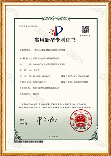
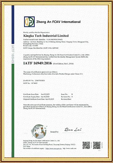
The company has obtained ISO 9001 quality management system certification (GB/T 19001-2016 idt ISO 9001:2015) , IATF 16949:2016 and RoHS test reports, and has also secured a patent for a manufacturing apparatus for a GPU immersion cooling system.

Liquid Cold Plates FAQ
What is a liquid cold plate?
A liquid cold plate is a heat exchanger that transfers heat from an electronic or mechanical component into circulating coolant. Internal channels carry the coolant close to the heat source so thermal energy can be removed efficiently.
What is the difference between a cold plate and a water block?
The two terms describe very similar thermal devices. “Water block” is commonly used for CPU and GPU cooling, while “liquid cold plate” is a broader industrial term covering cooling components used in batteries, power electronics, medical equipment, lasers, semiconductor systems and industrial equipment.
What materials are used for liquid cold plates?
Aluminum and copper are the most common materials. Aluminum provides good thermal performance with low weight and cost, while copper provides higher thermal conductivity for concentrated heat loads.
What coolant is used in liquid cold plates?
Common options include water and water-glycol mixtures. Some applications require dielectric or specialized engineered fluids. Coolant selection should consider thermal performance, operating temperature, corrosion and material compatibility.
What is an FSW liquid cold plate?
An FSW liquid cold plate uses Friction Stir Welding to seal machined coolant channels between the cold plate base and cover. This allows customized channel geometries to be produced without conventional fusion welding.
What is a tube liquid cold plate?
A tube liquid cold plate contains formed coolant tubing embedded into a metal base, usually an aluminum plate. Copper tubes are commonly used to transport coolant underneath heat-generating areas.
What is a brazed liquid cold plate?
A brazed liquid cold plate uses brazing to join the base, cover and internal cooling structures. The process enables complex channels, fins and other internal structures to be integrated into a compact cold plate.
Does increasing coolant flow always improve cooling?
Higher flow generally improves convective heat transfer, but the improvement becomes smaller as flow increases while pressure drop and pumping requirements continue to rise. Flow rate must therefore be optimized together with channel geometry.
What determines liquid cold plate performance?
Important factors include heat load, heat flux, coolant inlet temperature, flow rate, cold plate material, channel geometry, thermal contact resistance and pressure drop.
Can liquid cold plates be customized?
Yes. Cold plate dimensions, channel geometry, inlet and outlet locations, mounting holes, material, surface finish, coolant configuration and manufacturing technology can all be customized according to the application.